specifications
Maximum power(Pmax) 120W
Output tolerance ± 3%
Maximum system voltage 700V DC
Open circuit voltage(Voc) 21.6V
Short circuit current(Isc) 6.82 A
Maximum power voltage(Vmp) 18V
Maximum power current(Imp) 6.5A
Operating temperature(NOCT) 45±2℃
Temperature range -40℃~+80℃
Number of cells 36pcs
Weight 2200g
Size 1170*540*2.5 mm
Color Black Standard Test Conditions : lrradiance 1000w/m^2,Temperature 25℃, AM=1.5
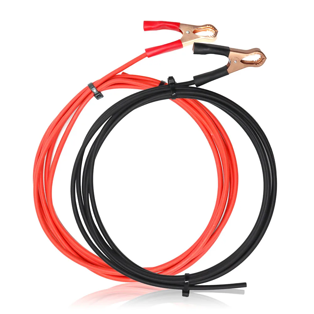
(220V 1000w 720W )Package Includes:
(110V 1000w 720W )Package Includes:

(220V 1000w 600W )Package Includes:
(110V 1000w 600W )Package Includes:

(220V 1000w 480W )Package Includes:
(110V 1000w 480W )Package Includes:

(220V 1000w 360W )Package Includes:
(110V 1000w 360W )Package Includes:

(220V 1000w 240W )Package Includes:
(110V 1000w 240W )Package Includes:

(220V 1000w 120W )Package Includes:
(110V 1000w 120W )Package Includes:


 Solar panel systems need to be equipped with batteries for use together
Off-Grid Solar System User Manual
Use attention
1. Please install the solar panel system in cloudy days. If installing in strong light, pay attention to protection against electric shock.
2. Normally red color is the positive electrode and black color is the negative electrode. The positive and negative electrodes must be installed correctly. Do not directly connect the positive and negative poles of the solar panel to avoid a short circuit.
3. Do not scratch or step on the solar panel during installation and use. Check in advance whether the controller, battery, inverter and other accessories are normal.
Installation process
1. First, connect the battery to the controller to activate the controller. There is no display if only the solar panel is connected to the controller.
2. Then connect the solar panels, please install solar modules in a sunny and shadowless area. When using a 12V system, configuring 12V batteries and 16V/18V solar panels, so multiple solar panels need to be connected in parallel. When using a 24V system, configuring 24V batteries and 32V/36V solar panels, so every 2 solar panels need to be connected in series. Then connect all pairs in parallel. And so on. The parallel requires the same voltage, especially the series requires the same current.
The schematic diagrams of parallel and series connection of solar panels are as follows
(the same applies to batteries):


First, connect the inverter wire to the positive and negative poles of the inverter and tighten them. And then connect the other end of the wire to the positive and negative poles of the battery. It is normal if there is a small spark. Then connect the load to the inverter and turn on the inverter switch to start the load.
Do not connect the inverter to the controller to avoid damage.
 Safety Instructions:
1.Make sure your battery has enough voltage for the controller to recognize the battery type before first installation.
2.The battery cable should be as short as possible to minimize loss.
3.The regulator is only suitable for lead acid batteries: OPEN, AGM, GEL,lithium ions batteries).
4.The charge regulator is only suitable for regulating solar modules. Never connect another charging source to the charge regulator.
System Connection:
1.Connect the battery to the charge regulator - plus and minus.it will show 1 ,if it detects 12V battery, 2 if it detects 24V battery.
2.Connect the photovoltaic module to the regulator - plus and minus.
3. Connect the consumer to the charge regulator - plus and minus.


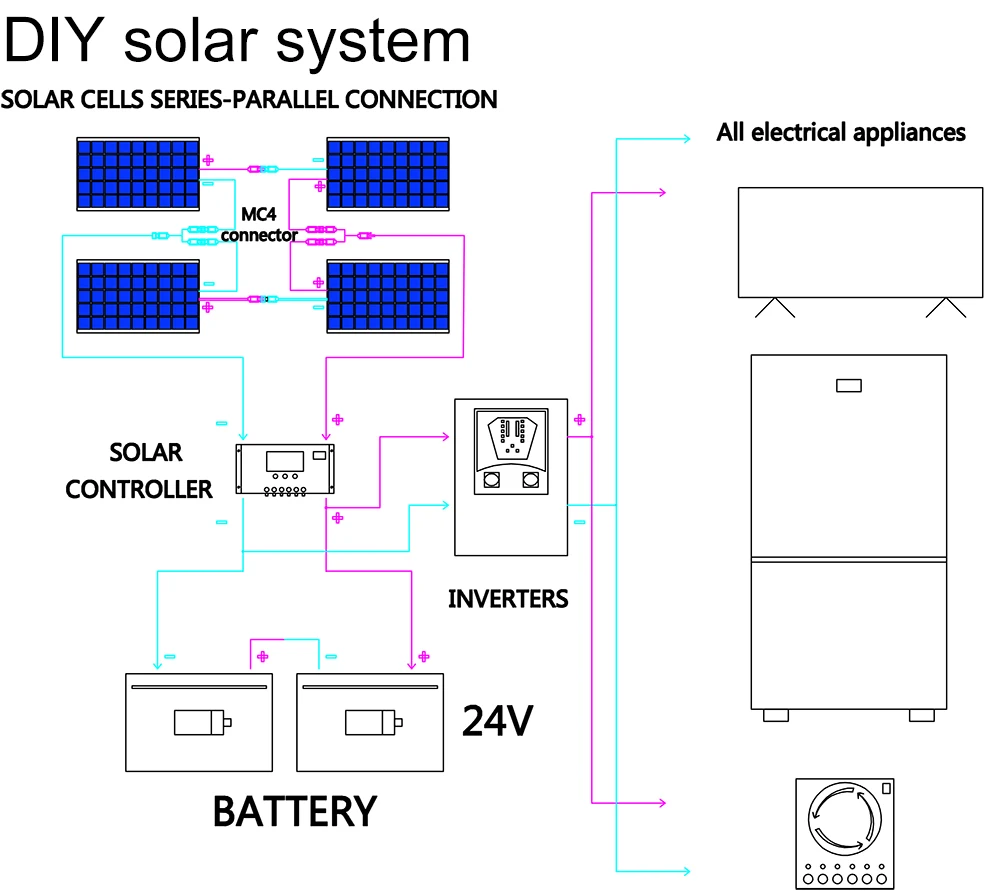
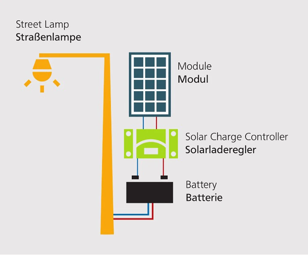
 SOLAR HOME SYSTEM
• Small DC systems
• Telemetry use
• Home use
• Holiday houses
• Garage lighting
• Recreational use • Lighting of streets in regions without
reliable grid
• Billboard lighting
• Sports field lighting
• Parking space lighting
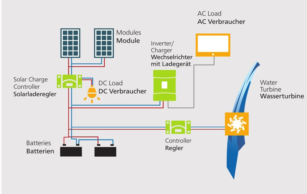
 • AC and DC loads possible
• Home use
• Industrial use
 HYBRID SYSTEM
• PV and wind turbine or diesel generator
• DC and AC loads possible
• High reliability
• Small hydro generators

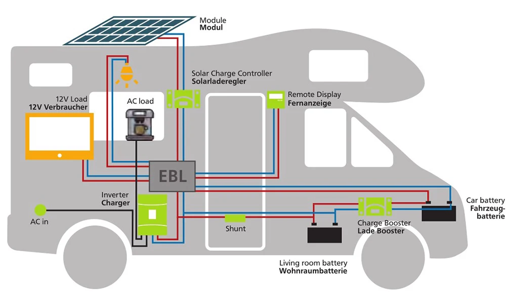
 • Recreational use
• Caravan and camping
OFF-GRID CONNECT
• Covering self consumption
• Grid is used as back-up
• Reduces energy cost