This link has solar panels, solar panel kits, inverters to choose from, when you order please note that you need to choose the solar panel module
However, the zip code in Spain that starts with 35, 38, 51, 52 need Shipping from China (Customs clearance fees may apply)
Packing listing:
1. 1 pcs 100w solar panel
2. 10A 12v/24v charge controller
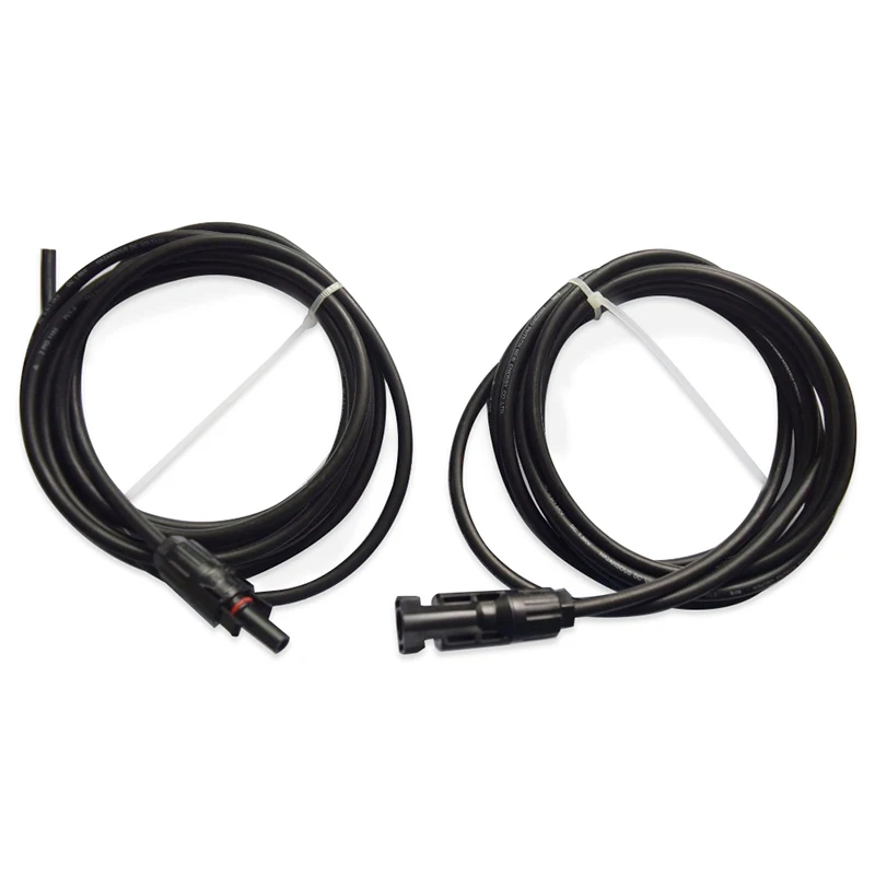
3. 1 set Extension cable with PV connector
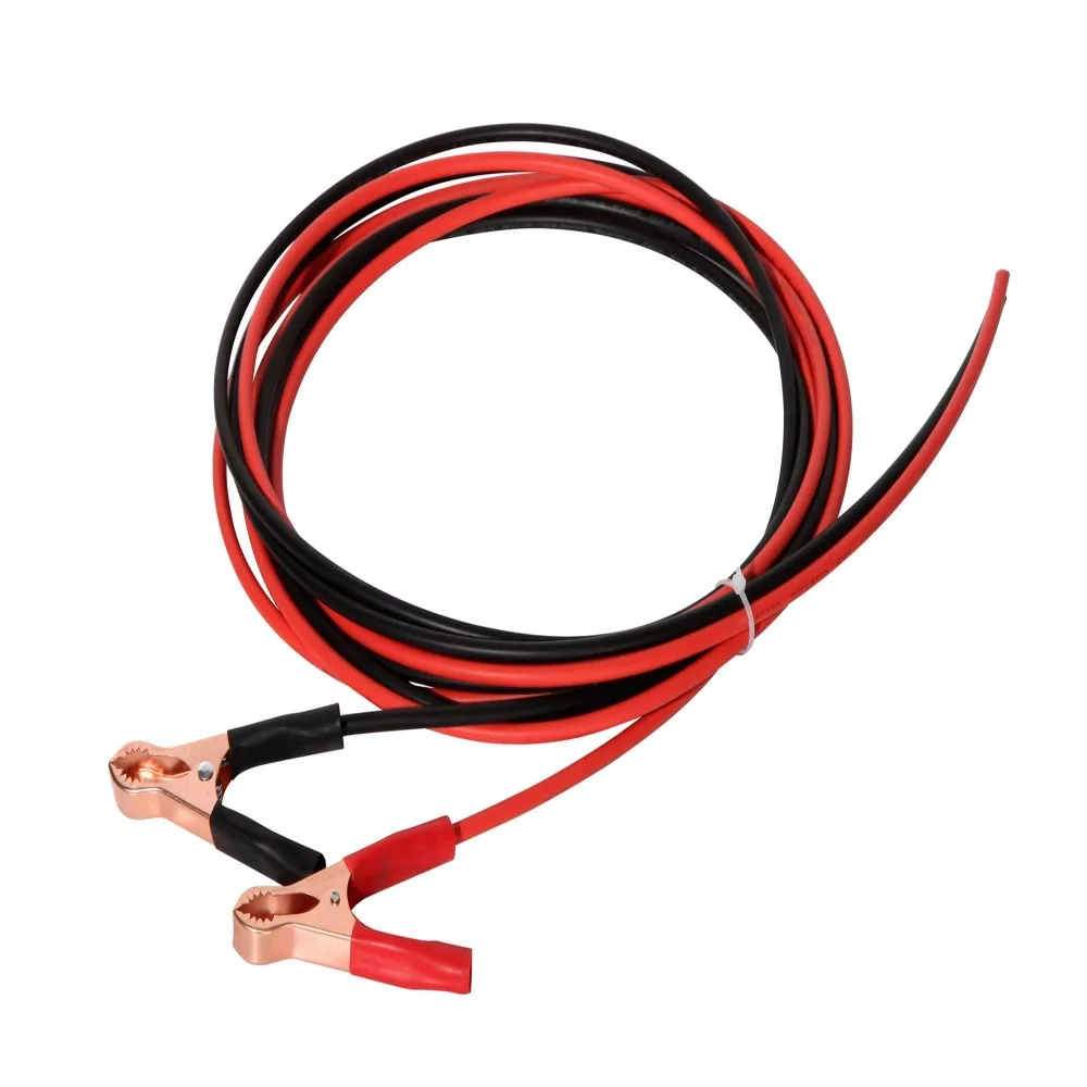
4. 1 set cable with alligator clip (connect to battery)

200W kit
Packing listing:
1. 2pcs 100w solar panel
2. 20A 12v/24v charge controller
3. 1 set Extension cable with PV connector
4. 1 set cable with alligator clip (connect to battery)
5. 1 set 2 in 1 PV connector (in parallel solar panel

Packing listing:
1. 3pcs 100w solar panel
2. 30A 12v/24v charge controller
3. 1 set Extension cable with PV connector
4. 1 set cable with alligator clip (connect to battery)
5. 1 set 3 in 1 PV connector (in parallel solar panel

400W kit (4pcs 100w solar panel kits)
Packing listing:
1. 4pcs 100w solar panel
2. 40A 12v/24v charge controller
3. 1 set Extension cable with PV connector
4. 1 set cable with alligator clip (connect to battery)
5. 1 set 4 in 1 PV connector (in parallel solar panel

Features:
a. Select high-efficiency 158*158mm lines monocrystalline silicon solar cells, the power generation efficiency is about 1.3 times that of conventional polysilicon, and the overall area is smaller at the same power.
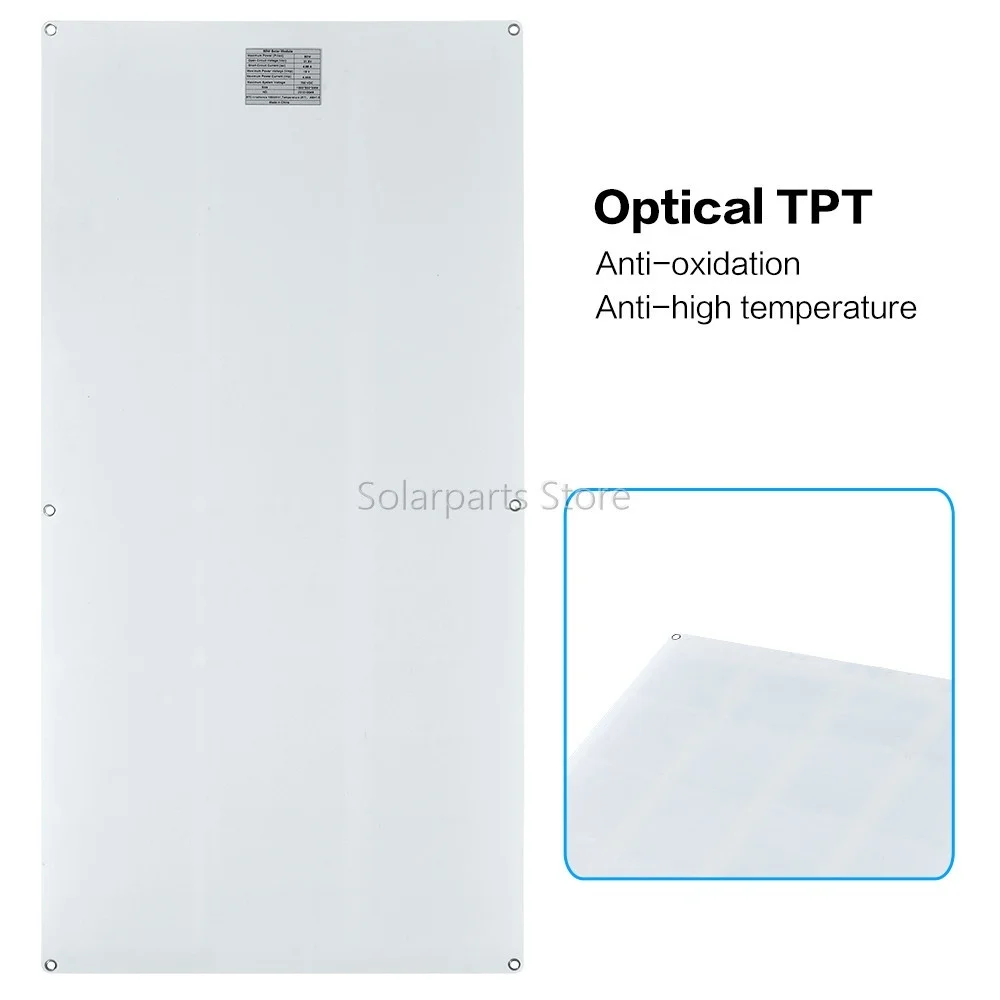
b. Semi flexible design,Graceful appearance, delicate and cabinet;
c. The surface is made of PET and treated with a special process, which is more wear-resistant and improves the absorption efficiency of sunlight.
d. Convenience to take , fashionable elegance. PV connector can be suitable to connect controller.
Especially suitable for anywhere can obtain sunshine, realize high-efficient charging, use convenient and safe, environmental protection, energy saving.It is good for promotion, sales, gifts etc.
e. The junction box adopts IP67 waterproof design, contains bypass diode, and the circuit adopts overcharge and reverse current protection design.
f. Use photovoltaic special cable and PV connector, outdoor use is safe, waterproof, high temperature resistance and weather resistance. PV connector is easy to use, plug and play.
g. This product is a solar module. It is recommended to be used with controllers and batteries. It can be used in various scenarios such as households, camping, RVs, yachts, street lights and solar power stations.

Solar panel Technician Specification
Length | 1000mm | Weight | 1650 G |
Width | 500mm | Main material | Monocrystalline silicon |
Height | 2.5 mm | Frame material | PET+EVA+Cell+TPT |
Solar panel Electrical Specification
Performance Under Standard Test Conditions(STC*)
Maximum power | Pmax | 100 Wp |
Open circuit voltage | Voc | 21.6 V |
Maximum power point voltage | Vmpp | 18 V |
Short-circuit current | I sc | 6 A |
Maximum power point current | I mpp | 5.5 A |
Minor reduction in efficiency under partial load conditions at 25degC: at 100 W/m2, 95%- (+/-3%) of the STC efficiency (1000 W/m2) is achieved.
Solar panel Component Material
Cells per module | 36 | Cell dimensions | 158mm*158mm/158*79mm |
Cell type | Monocrystalline Silicon | Front | EVA+Plastic Cover |
System Intergration Technician
Maximum system voltage SC II | 1000 V | Maximum reverse current | 10 A |
Maximum system voltage USA NEC | 600 V | Increased snowload acc. to IEC 61215 | 5.4 kN/msup2; |
Thermak Characteristics
NOCT | 47 degC | TC Voc | -0.33 %/degC |
TC Isc | 0.042 %/degC | TC Pmpp | -0.45 %/degC |
Solar panel Extra Specification
PTC rating | 100 W | Module efficiency | 22.0% |
Junction box | IP67 | Plus-Sorting* | Pflash ge Pmax |
Cable Length | 0.9 M | Power tolerance* | +/- 5 % |



 Controller connection instructions
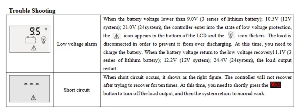
a Before connecting the solar panel, please connect the controller to the battery first. Connecting the solar panel without connecting the battery may cause the controller to burn out and fail to display.
b After the controller is connected to the storage battery, connect the above-mentioned series or parallel solar panels to the controller through the transfer cable.
c Finally, connect the required DC load to the load end of the controller. If the load does not work, press the third button of the controller.
d According to the controller manual, adjust the parameters you need.


1set 3M cable with alligator clip(Connect the battery)
Packing listing:
1. 1pcs 100w solar panel

Packing listing:
1. 2pcs 100w solar panel

specifications
Maximum power(Pmax) 120W
Output tolerance ± 3%
Maximum system voltage 700V DC
Open circuit voltage(Voc) 21.6V
Short circuit current(Isc) 6.82 A
Maximum power voltage(Vmp) 18V
Maximum power current(Imp) 6.5A
Operating temperature(NOCT) 45±2℃
Temperature range -40℃~+80℃
Number of cells 36pcs
Weight 2200g
Size 1170*540*2.5 mm
Color Black Standard Test Conditions : lrradiance 1000w/m^2,Temperature 25℃, AM=1.5


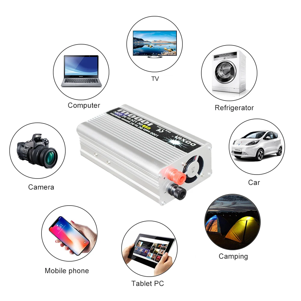
1000W inverter
Packing listing:
1. 1pcs 1000w solar inverter
(The inverter has four specifications to choose from
12V to 110V 1000W inverter
12V to 220V 1000W inverter
24V to 110V 1000W inverter
24V to 220V 1000W inverter)




Notes for use:
a. This product must not come into contact with highly corrosive substances.
b. It is strictly forbidden to modify, disassemble, drop, and hit the junction box and products by yourself, avoid stepping on the surface and scratching the surface with hard objects during use.
c. A large number of scratches or dirt on the surface of the solar panel may cause the solar cell module to be inefficient, and in severe cases may cause burnout.
d. The suitable ambient temperature range of this product: -20 ° C-80 ° C, please do not exceed this range.
e. The solar panel must be installed in an area with good sunlight and no shadow. The long-term work of the solar cell module in the sun with shadow may have the risk of burning.
f. It is forbidden to connect the positive and negative poles of the product together, and it is forbidden to put the product into water or fire, otherwise it will damage the product.
g. The overall power of the photovoltaic module must be less than the rated power of the controller (rated voltage × rated current). It is strictly prohibited to overload the controller.
h. The total voltage of the photovoltaic module connected to the controller must be within the photovoltaic input voltage range of the controller.
i. The inverter can only be connected to the battery, not directly to the controller.
Off-Grid Solar System User Manual
Use attention
Use attention
1. Please install the solar panel system in cloudy days. If installing in strong light, pay attention to protection against electric shock.
2. Normally red color is the positive electrode and black color is the negative electrode. The positive and negative electrodes must be installed correctly.
Do not directly connect the positive and negative poles of the solar panel to avoid short circuit.
3. Do not scratch or step on the solar panel during installation and use. Check in advance whether the controller, battery, inverter and other accessories are normal.
Installation process
1. First connect the battery to the controller to activate the controller. There is no display if only the solar panel is connected to the controller.
2. Then connect the solar panels, please install solar modules in a sunny and shadowless area. When using a 12V system, configuring 12V batteries and 16V/18V solar panels, so multiple solar panels need to be connected in parallel. When using a 24V system, configuring 24V batteries and 32V/36V solar panels, so every 2 solar panels need to be connected in series, then connect all pairs in parallel. And so on. The parallel requires the same voltage, especially the series requires the same current.
The schematic diagrams of parallel and series connection of solar panels are as follows
(the same applies to batteries):

3. Next, connect the inverter to the battery, and finally connect the load to the inverter. The low-power DC load can be directly connected to the controller, and the AC load needs to be connected to the inverter.
First connect the inverter wire to the positive and negative poles of the inverter and tighten them, and then connect the other end of the wire to the positive and negative poles of the battery. It is normal if there is a small spark. Then connect the load to the inverter and turn on the inverter switch to start the load.
Do not connect the inverter to the controller to avoid damage.
